ACF-Heat Seal Bonding
Unsere Montage-Experten sind spezialisiert im ACF-Heat Sealing von Elektronikkomponenten an empfindliche Sensor-Panels. Kontaktieren Sie uns bei Fragen zur HSB-Verbindungstechnik oder Ihren Möglichkeiten mit dem ACF-Heat Seal Bonding-Verfahren von CrossTEQ.
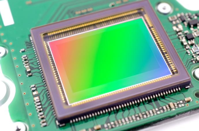
ACF-HSB Verfahren für die Herstellung von grossen Bildsensoren
In cooperation with our partner Getronic Engineering AG, CrossTEQ has co-developed a specific, semi-automated ACF heat seal bonding process for the production of highly sensitive, large area X-ray image sensor panels in medical technology. In the developed process, flexible printed circuit boards (Flex PCBs) with a conductor pitch of only 0.150mm and a conductor width of only 0.100mm are contacted to an amorphous silicone-based base plate.
Was ist die ACF-Heat Seal Bonding Verbindungstechnik
Anisotropic conductive bonding (ACF-HSB for Anisotropic Conductive Film Heat Seal Bonding) is a bonding technique for the precise contacting of flexible conductive tracks to a base medium, such as an LCD panel. By using flex films and anisotropic conductive adhesive (in which the electromagnetic properties depend on the direction, whereas with isotropic materials the electromagnetic properties are the same in all directions), ACF-Heat Seal Bonding can be used to join almost any material in a visually appealing way and to achieve a uniform distribution of adhesive force without thermal stress or degradation of the material.
Das sind die Verbindungseigenschaften von ACF-HSB vs. HSC
Heatseal connections have a relatively high resistance and a low maximum current density. The electrical resistance is in the range of 2-10 Ω for PCB connections and 10-100 Ω for LCD connections. Insulation resistance is in the 109-10 Ω range. ACF can withstand temperatures up to +80 to +120 °C while for HSC the effective temperature comparison is -40 to +60 °C.
Contact us with any questions about HSB bonding technology or your options with CrossTEQ's ACF Heat Seal Bonding process.
Wir sind spezialisiert im ACF-Heat Sealing von Elektronikkomponenten an empfindliche Sensor-Panels und helfen Ihnen gerne weiter. Kontaktieren Sie uns!
Why ACF-Heat Sealing?
Anisotropic conductive (ACF) heat seal bonding has an extremely high bonding quality, which is why there is a strong shift towards this bonding technique in the manufacturing industry. The explosion in the use of displays, as well as new developments in production technology such as vision-assisted automatic alignment and fully automated Anisotropic Conductive Foil modules, have recently paved the way for widespread use of this technique.
ACF-HSB Process
Before the connection, an insulating adhesive film separates the conductive particles. When a heating element presses the top and bottom circuit boards together with the adhesive in between, the adhesive flows and the conductive particles are trapped, resulting in an electrical connection.
With anisotropic heat sealing, compression only occurs in the direction of the Z-axis, which is why an electrical connection is only made in this direction. Due to the low filler content (1-5 %), a short circuit between adjacent conductive paths cannot take place.
The adhesive is usually a blend of thermoplastic and thermosetting (also known as thermoset) adhesives to get the best of both properties. Thermosetting adhesives require a higher temperature and longer cure time than thermoplastic adhesives. Due to their higher melting temperature needs, polyamide film is most commonly used for this purpose.
- Massive conductive particles
- massive Kunststoffteilchen, beschichtet mit leitfähigem Material
- hohle Kunststoffteilchen, die mit leitfähigem Material
Am häufigsten verwendet werden massive Graphitpartikel, Goldpartikel und vergoldete Kunststoffteilchen. Graphitpartikel sind scharf, was ein Vorteil sein kann, wenn eines der zu verbindenden Materialien eine dünne isolierende Oxidschicht aufweist. Die Nachteile sind, dass die Partikel nicht elastisch sind, was zu einem höheren Widerstand führt.
In addition, graphite particles are hygroscopic. Attracted moisture can affect the adhesive matrix and cause corrosion between the contacts.
Da Gold nicht hygroskopisch ist, wird es manchmal gegenüber Graphit bevorzugt. Auch der Kontaktwiderstand ist geringer als bei Graphitpartikeln. Vergoldete Kunststoffpartikel sind komprimierbar, was zwei große Vorteile bietet:
Der Übergangswiderstand ist geringer, weil eine größere Oberfläche in Kontakt mit der oberen und unteren Bahn kommt. Das Teilchen wirkt außerdem wie eine Feder; eine kleine Entspannung des Klebers wird durch eine Ausdehnung des Partikels kompensiert, was zu einer besonders sicheren Verbindung führt.
leitfähige Folie
(Anisotropic
Conductive Film)
- If the ACF consists of three layers (the adhesive and two protective layers), one layer is peeled off before the first process step. Positioning of the adhesive and the protective layer on the bonding surface, with the protective layer facing the thermode.
- The material is pre-sealed: It is heated to 80 °C for a few seconds to bond it to the display or PCB.
- The last protective layer is removed.
- The Flex-connector is placed on the ACF and aligned.
- Die Endversiegelung erfolgt bei einer Temperatur von 150-180 °C im Kleber für 10-30 Sekunden.
ACF-Flex connection design
Die Leiterbahnen des Flexverbinders bestehen normalerweise aus 12,5 oder 25 µm dickem, passiviertem Kupfer oder Löt- oder Zinnbeschichtungen.
Bei CrossTEQ verwenden wir vergoldete Kontakte, da sie am zuverlässigsten sind.
Die meisten Flexes haben drei Schichten, mit einer dünnen Kapton-Schutzschicht auf der Unterseite des Flexes, um die Belastung der Verbindung so gering wie möglich zu halten.
Display Design
In general, the contact areas should be kept as small as possible because the display areas on the displays should be as large as possible compared to the outer dimensions of the display. In most cases, an area along the entire length of the display is available for the connections. The width of the connector can vary. Normally, this width is 3 or 3.5 mm.
Positioning and final alignment
We use a microscope to achieve the necessary magnification and good contrast during active positioning. Alignment can be performed on special markings (such as crosses, thick tracks, curves, etc.) on the tracks themselves.
Die Ausrichtung der Teile kann auch passiv (am besten mit Referenzlöchern) erfolgen. Es ist wichtig, die Löcher so nah wie möglich an der Anzeige (Leiterplatte) zu positionieren, um eine maximale Genauigkeit zu erreichen.